Types of electrical elements
Electrical elements are categorized in many ways :
- Active and Passive elements.
- Linear and Non-linear elements.
- Unilateral and Bilateral elements.
- Time variant and Time invariant elements/circuit.
- Lumped and Distributed elements model.
So let us discuss each of them one by one.
Active and Passive elements
Active element
These are the property of an active element. If any electrical elements have at least one of these properties, it is called an active element.
- Active elements provide power to an electrical circuit for a long time.
- Active elements can control the flow of charge in a circuit.
- It has the ability to amplifies the power of a signal (voltage or current).
- It requires an external source for operation.
Example of active elements are:
- Voltage sources, current sources, generators
- Transistors (such as BJT, MOSFETS, FETs, JEFT)- Transistors are used to amplify electrical signals. So, it is an active element.
- Diodes (such as Zener diodes, Photo diodes, Schottky diodes, LEDs).
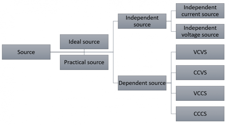
Ideal independent voltage source
An ideal independent voltage source is an active element that provides a specified voltage that is completely independent of other circuit elements.
An ideal voltage source delivers to the circuit whatever current is necessary to maintain terminal voltage. Example: Batteries, generators may be considered as an approximation to ideal independent voltage sources. In real life, practical independent voltage sources exist which we discuss in this article later. In the below fig no. (a) and (b) figure of the ideal independent voltage source is given.
Ideal independent current source
An ideal independent current source is an active element that provides a specified current that is completely independent of other circuit elements.
In other words, An ideal current source delivers to the circuit whatever voltage is necessary to maintain the designated current. Example: Van de Graaff generator can supply the same small current at almost any level of electrical potential, it is an example of a nearly ideal current source. In the below figure, a diagram of the ideal independent current source is given.
Ideal dependent source
An ideal dependent source is an active element in which the source quantity is controlled by another voltage or current. There are four possible types of dependent sources.
- Voltage-controlled voltage source:(VCVS) – A voltage-controlled voltage source is a voltage source that is controlled by another voltage elsewhere in the circuit. It is generally denoted by V=AVc where Vc is a controlling voltage and A is the gain term. Example: idealized amplifier.
- Current-controlled voltage source (CCVS) – This is a voltage source whose value is controlled by a current elsewhere in the circuit. Its output is typically given as V=AIc, where A is a gain term and Ic is a control current.
- Voltage-controlled current source (VCCS)- This is a current source whose value is controlled by a voltage elsewhere in the circuit. Its output is typically given as I=AVc, where A is a gain term and Vc is a control voltage.
Current-controlled current source (CCCS)- A current controlled current source is a current source whose value is controlled by another current elsewhere in a circiut. It is generally denoted by I=AIc, where Ic is controlling current. Example:BJT.
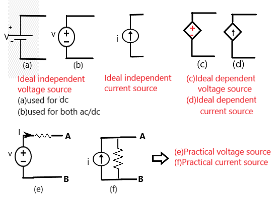
Practical voltage source
Practically, voltage source has a finite amount of internal resistance (impedance). We represent it by connecting internal resistance in series with an ideal voltage source [Shown in above figure no. (e)].
Difference between a practical and ideal voltage source:
Ideal voltage source
- The value of internal resistance is zero, which means it has no internal resistance
- It will produce any current to maintain the designated terminal voltage. Thus, an ideal voltage source can supply an infinite amount of energy.
- It provides constant voltage independent of load types.
- VAB=V [From the above figure no. (e)] because internal resistance is zero.
Practical voltage source
- It has some finite internal resistance connected in series. As the value of internal resistance approaches zero it starts to become an ideal voltage source.
- It cannot provide unlimited current.
- It cannot provide constant terminal voltage for every load because of voltage drop due to internal resistance.
- VAB=V-IR [From the above figure no. (e)], where R≠0.
Practical current source
Practically, the current source also has a finite amount of internal resistance. We represent it by connecting internal resistance in parallel with an ideal current source [Shown in above figure no. (f)].
Difference between a practical and ideal current source:
Ideal current source
- The value of internal resistance is infinite. So, that whole current passes through the load.
- It will produce any voltage to maintain the designated current. Thus, an ideal current source can supply an infinite amount of energy.
- It provides a designated amount of current independent of load type.
- I(output)=i because internal resistance is infinite.[figure no. (f)]
Practical current source
- It has some finite internal resistance connected in parallel. As the value of internal resistance approaches infinite it starts to become an ideal current source.
- It cannot provide unlimited power because as VAB increases the output current decreases.[figure no. (f)]
- It cannot provide the same current output for every load type because of the current division.
- I(output)=i-(VAB/R), where the value of R is not infinite.[figure no. (f)]
Passive element
- Passive elements are not capable to provide energy on their own.
- It utilizes and stores energy in a circuit.
- It is used for energy storage, discharge, oscillating, filtering, and phase shift application.
- It does not require any external source for operation.
- It cannot control or amplify the signal.
Example of passive elements are:
- Resistor: Resistor dissipates energy in the form of heat in a circuit .so, it is a passive element.
- Capacitor: Capacitor store electrical energy in the form of an electric field and it also discharges energy sometimes. So, it is a passive element.
- Inductor: Inductor stores electrical energy in form of the magnetic field. Hence it is a passive element.
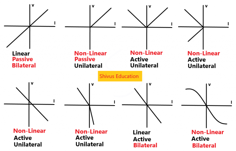
Graphical representation of active and passive elements
How do we determine the electrical element is active or passive by analyzing its V-I characteristics graph? Before knowing it let’s know what is V-I characteristics of an electrical element?
V-I characteristics give the relation between the voltage across element and current through it. If the part of the V-I characteristics graph of an element lies in the second and fourth quadrant then it is an active element otherwise passive element.
Linear and Non-linear electrical element
A function is linear if it has these properties:
- Homogeneity(scaling) : f(ax)=af(x)
- Additivity : f(x1+x2)=f(x1)+f(x2)
When the inputs and outputs are single numbers, a function that has the scaling property automatically has additivity as well. Resistors, capacitors, and inductors are linear because they have the scaling property.
Linear element
Those electrical elements whose V-I characteristics are linear called linear elements. For example resistor, capacitor, inductor, transformer, etc.
A resistor may be linear or non-linear. Linear resistor follows OHM,s law while non-linear resistor does not follow OHMs law.
V(I)=IR
let us check it is linear or not
Homogeneity: V(aI)=aIR=aV(I).
Additivity: V(I1+I2)= (I1+I2)R = I1R+I2R = V(I1)+V(I2).
Hence V=IR follows the linear property. Similarly for capacitor and inductor.
Linear circuit
Electrical circuits are those circuits whose parameters(resistor, insulator, capacitor ) are constant. In other words whose parameter does not change with respect to current and voltage. Current flowing through a linear circuit is directly proportional to the applied voltage or vice-versa.
Non-linear element
Those electrical elements whose V-I characteristics are not linear called non-linear elements. For example non-linear resistors, transistors, diodes, vacuum tubes, iron core inductors, other semiconductor devices, transformers, etc. Non-linear elements do not follow OHMs law.
Non-linear circuit
Electrical circuits having non-linear element is called a non-linear circuit. In other words the parameter of the non-linear circuit changes with respect to time.
Graphical representation of linear and non-linear elements
If the V-I characteristics graph of an electrical element is a straight line passing through the origin then it is called a linear element otherwise a non-linear element.
Unilateral and bilateral element
Unilateral element
- The property of unilateral elements changes with the change in direction of supply voltage or current.
- It allows the conduction of current only in one direction.
- Example: Diode, transistor
Bilateral element
- Property of bilateral elements does not change with the change in direction of supply voltage or current.
- Conduction of current in both directions in an element with the same magnitude.
- Example: Resistor, capacitor, inductor, etc.
Graphical representation of unilateral and bilateral elements
If the V-I characteristic of an electrical element is symmetry with respect to origin (i.e; the first and third quadrant are in symmetry and the second and fourth quadrant is in symmetry) then it is a bilateral element otherwise unilateral.
Time-variant and time-invariant elements/circuits
When the V-I characteristic of a circuit or an element is changed with time then the circuit or that element is called time-variant otherwise time-invariant.
Lumped and distributed elements model
Lumped element model
- When we take electrical elements values considering it concentrated at a point.
- We use it when the size of the electrical element is very small as compared to the wavelength of voltage and current.
- The electrical circuit in which lumped element model is used is called lumped circuit model.
- Used in electronic circuit
Distributed element model
- It is based on considering electrical elements distributed in space.
- We use it when the size of the electrical element is comparable to the wavelength of voltage and current.
- The electrical circuit in which distributed element model is used is called distributed circuit model.
- Used in transmission and distribution lines.