Kirchhoff's laws- KCL and KVL
Ohm’s law is not sufficient to analyze electrical circuits. If we combine it with Kirchoff’s laws, we have a sufficient, powerful set of tools for analyzing a large variety of circuits. Kirchhoff’s laws were first described in 1845 by German physicist Gustav Kirchhoff.
There are two Kirchhoff’s laws:
- Kirchhoff’s current law (KCL).
- Kirchhoff’s voltage law (KVL).
Let us discuss both laws one by one in detail.
Kirchhoff’s current law (KCL)
- KCL is based on the law of conservation of charge that is the algebraic sum of charges within a system cannot change.
- KCL (Kirchhoff’s current law) states that the algebraic sum of currents entering a node(or a closed boundary) is zero.
- We can also take the algebraic sum of currents leaving a node.
- Mathematically ,
\[\sum_{n=1}^N i_n=0 \]
where N is the number of branches connected to the node. And in is the current leaving(or entering) through the nth branch.
Note: In this equation, we take all current as leaving or all current as entering not both. - In other words, we can define KCL as the total current entering a node is equal to the sum of the currents leaving the node.
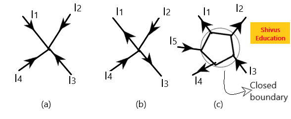
In figure no. (a) I1, I2, I3, and I4 are four currents entering at a node and there is no current leaving the node.
So, I1+ I2+I3+I4=0
⇒Total current entering a node= Total current leaving the node.
In figure no. (b) I1 and I3 currents are leaving the node while I2 and I4 currents are entering the node. For applying KCL we take all current as entering so we can say that -I1, I2, -I3, and I4 are four currents entering the node.
So,-I1+ I2-I3+I4=0⇒I2+I4=I3+I1
⇒Total current entering a node= Total current leaving the node.

KCL also applies to a closed boundary. As shown in above figure no. (c), I1, I2, and I4 are three currents leaving the closed boundary. While currents I3 and I5 are entering the node. For applying KCL we take all currents as leaving (we can also take all current as entering) so we can say that I1, I2, -I3, I4, and -I5 are currents leaving the closed boundary.
I1+I2 -I3+ I4-I5 =0
⇒I1+I2 +I4=I3+I5
⇒Total currents leaving a closed boundary=Total current entering the closed boundary
Application of KCL
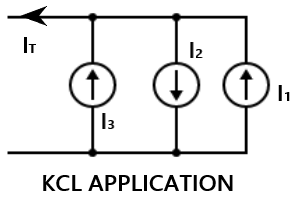
When current sources are connected in parallel, KCL can be applied to obtain a combined current.

Let us take all currents as leaving the upper node and apply KCL we have
IT-I1 +I2-I3 =0
⇒IT=I1 -I2+I3
Note:1. When current sources are connected in parallel, the combined current is the algebraic sum of current supplies by individual sources.
2. A circuit cannot contain two different currents, I1 and I2, in series unless I1=I2; otherwise KCL will be violated.
Kirchhoff’s voltage law(KVL)
- KVL is based on the principle of conservation of energy.
- It states that the algebraic sum of all voltages around a closed path(or loop) is zero.
- Mathematically,
\[\sum_{n=1}^N V_n =0 \]
where N is the number of voltages in the loop and Vn is the nth voltage.
How to apply KVL in electrical circuits?
- First, mark the voltages with the sign for each electrical element. If voltage is unknown then suppose it by yourself with any sign. If the value of this unknown voltage comes negative means you have supposed the wrong polarity and changed it.
- Now start from any voltage and go around the loop either clockwise or anti-clockwise.
- If the polarity of voltages comes from positive to negative we take voltage drop as -ve voltage. And if the polarity of voltage comes from negative to positive we take voltage rise as +ve voltage. [Not necessary to take in the same way you can take opposite to it, but whatever rule you apply, apply for all voltages]
- Write the KVL equation and solve it.

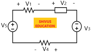
If we go in the clockwise direction and start from voltage V1 then
- V1, V2, and V4 are from positive to negative which means voltage drop i.e, -V1, -V2, and -V4.
- V3 and V5 are from negative to positive which mean voltage rise i.e, +V3 and +V5.
Putting all the voltages in the KVL equation we have
-V1-V2+ V3 -V4 +V5 =0
⇒ V3 +V5 =V1+V2+V4
⇒Sum of voltage drops= Sum of voltage rises
Application of KVL
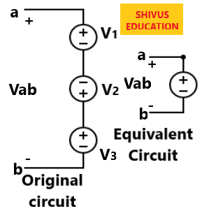
When voltage sources are connected in series, KVL can be applied to obtain total voltage.

By applying KVL to the above figure, we get
Starting from Vab and go around in the clockwise direction we have,
Vab-V1– V2 -V3 =0
⇒Vab=V1+V2 +V3
Note:1. When voltage sources are connected in series, the combined voltage is the algebraic sum of the voltages of the individual sources.
2.A circuit cannot contain two different voltages V1 and V1 in parallel unless I1=I2.