Inductance of single-phase two-wire transmission line
What will you learn?
- Internal flux linkage.
- External flux linkage.
- The inductance of a single-phase transmission line.
- Examples based on finding the inductance of a single-phase transmission line.
In this article, our final goal is to find the inductance of a single-phase wire. Consider a two-wire single-phase transmission line carrying current I. One wire is a Go conductor and the other is a return means in both conductor currents travel are equal in magnitude and opposite in direction. For finding the total inductance of the system first we will find the inductance of one conductor and then multiply it by two. For finding the inductance of one conductor(Let us say Conductor A)first, we have to derive the total flux linkage of that conductor.
Total flux linkage is divided into two parts:
- Internal flux linkage
- External flux linkage.
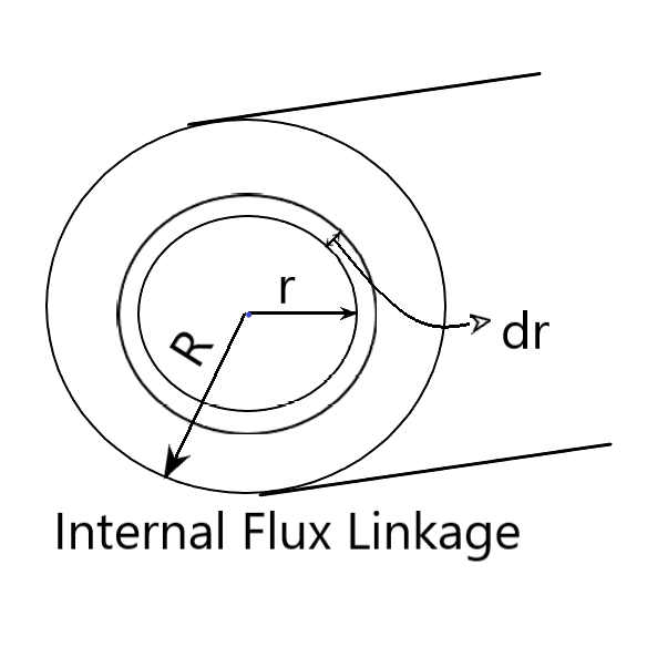
Internal flux linkage
Flux linkage due to flux lines inside the conductor is called internal flux linkage. In order to find internal flux linkage, we will consider the magnetic field intensity(H) at a distance r<R.
\[\oint \vec{H}. \vec{dl} =I_{enclosed}\\ \Rightarrow H \times 2 \Pi r=I_{enclosed}\\ \Rightarrow H= \frac{I_{enclosed}}{2 \Pi r} \]
Here total current flowing in the conductor is I. Then total current flowing inside the radius r is-
\[I_{enclosed}= \frac{I}{ \Pi R^{2}} \times \Pi r^{2} =I \frac{ r^{2}}{ R^{2}} \]
By putting the value of Ienclosed in the above equation of H we have,
\[H= \frac{I r^{2} }{2 \Pi r R^{2}}= \frac{I r}{2 \Pi R^{2}}\\B= \mu H=\frac{ \mu I r}{2 \Pi R^{2}}\]Where B=Magnetic flux density.
The flux density is varying with r (Observation from the above equation of B) . But we can assume flux density to be constant over the infinitesimal distance dr. The flux lines are in the form of a circle. Thus flux lines passing through the concentric cylindrical shell of radii r and r+dr is:
dΦ=B×Area normal to flux density B
⇒dΦ=B×dr×l
Where l=length of wire.
Because we are interested in finding inductance per unit length thus we take l=1m.
\[d \phi =\frac{ \mu I r}{2 \Pi R^{2}}dr\]
Now, flux linkage(Ψ) = flux × number of turns
But here only a part of the conductor is being enclosed by flux lines dφ.
\[d \psi =d \phi \times \frac{ r^{2} }{R^{2} }=\frac{ \mu I r}{2 \Pi R^{2}}dr \times \frac{ r^{2} }{R^{2} }\\ ∴ d \psi=\frac{ \mu I}{2 \Pi R^{4}} r^{3} dr\]
Total internal flux linkage ψ:
\[\psi = \int_0^R d \psi = \frac{ \mu I}{2 \Pi R^{4}} \int_0^R r^{3} dr \\ \psi = \frac{ \mu I}{8 \Pi } \]
Note:- From the above equation, it is clear that the flux linkage due to internal flux is independent of the size of the conductor.
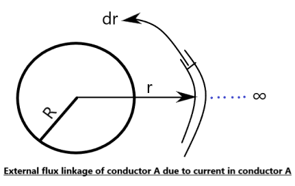
External flux linkage
Flux linkage due to flux line outside the conductor is called external flux linkage. The magnetic field intensity at any distance r (R≤r≤∞) is:
\[H= \frac{I}{2 \Pi r}\\B= \mu H= \mu_{0} \mu_{r} H\\B=\mu_{0} H\space\space [ \mu _{r}=1, For\space medium\space air]\\B= \frac{ \mu _{0}I}{2 \Pi r} \]
The flux density B can be considered constant over a distance dr. Thus the flux lines passing through the concentric cylindrical shells with radii r and r+dr will be :
dΦ=B.dA=B.dr.1=B.dr [for unit length]
where dA=Area perpendicular through which dΦ flux passes.
Since this flux encloses only one conductor, therefore the number of turns enclosed by this flux dΦ is one.
dΨ=dΦ × Number of turns=dΦ=B.dr
\[d \Psi = \frac{ \mu _{0}I}{2 \Pi r}.dr \]
Therefore total external flux linkages due to current flow in one conductor is Ψext :
\[\Psi _{ext}= \int_R^ \infty d \Psi = \frac{ \mu_{0}I}{2 \Pi} \int_R^ \infty \frac{dr}{r} \]
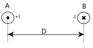
Important points:- This is the external flux linkage if there is only one conductor. But here we are finding external flux linkage of one conductor in presence of another conductor which is at distance D and having equal and opposite current flowing inside it. So, we have to consider flux linkage of the first conductor due to current in another conductor also. So for getting the total external flux linkage of one conductor in a single-phase transmission line we have two explanation /method:
Method 1
Total external flux linkage of one conductor in single-phase transmission line(Ψext )
=External flux linkage of conductor A due to current in the conductor A +External flux linkage of conductor A due to current in the conductor B
Current in conductor A=I
current in conductor B=-I
\[\Psi _{ext}=\frac{ \mu_{0}I}{2 \Pi} \int_R^ \infty \frac{dr}{r}-\frac{ \mu_{0}I}{2 \Pi} \int_D^ \infty \frac{dr}{r} \\\Psi _{ext}=\frac{ \mu_{0}I}{2 \Pi} \int_R^ D \frac{dr}{r}\\\Psi _{ext}=\frac{ \mu_{0}I}{2 \Pi}ln \frac{D}{R} \]
Method 2
At the time of finding magnetic field intensity (H), we use the formula:
\[H= \frac{I_{enclosed}}{2 \Pi r} \]
So, there is no flux line which is enclosing both the conductor because when the net current enclosed is zero, H will also become zero. Therefore we calculate external flux linkage from R to D-R. Since R is very small as compared to D, we can write D-R≅D
\[\Psi _{ext}=\frac{ \mu_{0}I}{2 \Pi} \int_R^ D \frac{dr}{r}\\ \Psi _{ext}= \frac{ \mu_{0}I}{2 \Pi}ln \frac{D}{R}\]
Inductance of a single-phase transmission line
Total flux linkage of conductor A=Internal flux linkage+ External flux linkage
\[\psi _{total}= \frac{ \mu I}{8 \Pi } + \frac{ \mu_{0} I}{2 \Pi } ln \frac{D}{R} \\ =\frac{ \mu_{0} \mu _{r} I}{8 \Pi } + \frac{ \mu_{0} I}{2 \Pi } ln \frac{D}{R}\\ = \frac{ \mu _{0}I}{2 \Pi } ( \frac{ \mu _{r}}{4} +ln \frac{D}{R}) \]
where μr is the relative permeability of the metal by which conductor is made.
The inductance of conductor A or Inductance per conductor (LA) is:
\[ =\frac{ Flux \space linkage \space of \space conductor \space A}{Current \space in \space conductor \space A} \\= \frac{ \frac{ \mu _{0}I}{2 \Pi } ( \frac{ \mu _{r}}{4} +ln \frac{D}{R}) }{I}\\L_{A}= \frac{ \mu _{0}}{2 \Pi } ( \frac{ \mu _{r}}{4} +ln \frac{D}{R})Henry/metre \]
Similary we can calculate LB and value of LB is same as LA because of symmetry.
Inductance of single-phase transmission line = Inductance due to both conductors:
\[L_{A}+L_{B}=2 \times L_{A} \space\space \\ [Since \space L_{A}=L_{B}]\\= \frac{ \mu _{0}}{ \Pi } ( \frac{ \mu _{r}}{4} +ln \frac{D}{R})Henry/metre \]
By putting the value of μ0 =4Π×10-7 and considering μr=1, we have
\[L=4 \Pi \times 10^{-7} [ \frac{1}{4} +ln \frac{D}{R} ]\\ = 4 \Pi \times 10^{-7} [ ln \space e^{\frac{1}{4}} +ln \frac{D}{R} ]\\ =4 \Pi \times 10^{-7} [ ln \frac{D}{Re^{- \frac{1}{4} }} ]\\=4 \Pi \times 10^{-7} [ ln \frac{D}{R’}]Henry/metre\\where R’=Re^{-\frac{1}{4}}=0.7788R \]
The R’ is the radius of that fictitious conductor assumed to have no internal flux linkages having the same inductance as the actual conductor of radius R. The multiplying factor of 0.7788 is to adjust the radius in order to account for internal flux linkages.